
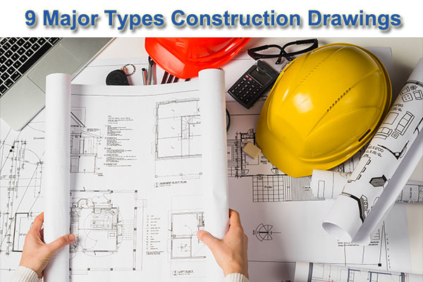
9 Most Common Types of Construction Drawing | Construction Drawing Importance
What is the definition of a Construction Drawing?
It’s a diagram that shows what will be built, how it’ll be laid out, the components, framework, and proportions. Every part of a construction project has a construction drawing that highlights the specifics.
Construction drawings, including all of their subtypes, are useful to numerous groups of workers who are responsible for performing or overseeing the many tasks that make up a construction project.
What are the steps involved in creating Building Drawings?
Construction blueprints are rarely drawn by hand these days. Computer-aided drafting software, such as computer-aided design (CAD) software, is used to draw and render them. Building Information Modeling (BIM) software has recently made it easier to create and visualize virtual construction models in greater detail (VCM).
Reach out to Monarch Innovation for any questions, assistance, or cooperation regarding BIM services, budgeting, and how they may benefit your project.
The following are the top 9 most popular types of construction drawings used in the construction industry.
1. Block Plan
This drawing depicts the arrangement of the site or the structures in the immediate vicinity, as depicted on a scaled map.
It gives you a firsthand view of the roads, boundaries, and other important facts that you’ll need to know about your construction site.
It helps the person dealing with your building plan or project request comprehend what you’re suggesting and where you’re proposing it, as well as assist you.
Block plans are drawn in relation to Ordnance Survey maps, with scales of 1:2500, 1:1250, or 1:500 being preferred.
2. Plans and elevations
Architectural drawings are drawings that are used in construction drawings to portray the proportions, depth, and layout of a building before it is built. Architectural drawings serve as a blueprint for the project, drawn to scale to aid engineers in visualising it.
The following are some of the most prevalent forms of architectural drawings:
Foundation Plan: The foundation layout should not be confused with the ground or basement floor plan. The foundation plans are the drawings that will be used to render any of the floors of the structure that is currently being built. They aid in visualising the dimensions, size, form, height, and arrangement of rooms/stairs/landings in relation to one another.
Floor plans: — a detailed rendering of the room layout for each floor. It depicts the alignment of rooms and components in two dimensions. Floor plans may or may not be used in commercial or non-commercial construction projects, but they must be drawn as part of the process.
Sectional Drawings: – These are drawings that show a sliced version of a section or the entire framework. It aids in comprehending the dimensions of various building components in relation to one another, the materials used in their construction, the height, depth, and hollowness of those components, and so on.
Elevation Drawings: – These architectural drawings provide a visual representation of the building’s numerous components, such as columns, windows, and doorframes. It also aids in understanding the surface, internal marks, and relative height of these many components in relation to one another.
3. Production Drawings
These Construction Drawings are used to communicate functional information to the on-site employees and engineers. It explains the materials, how to put various components together, the tools needed, the dimensions, and other information needed during the procedure. It might also give more details or an infographic on how to achieve the standards.
4. Structural Drawings
Structural drawings can also be used for civil engineering. They’re important for deciphering the physical details of a structure’s framework. For the employees and on-site engineers, they serve as a structural design guide. The following are examples of structural drawings:
General Note – a summary of all the codes, processes, abbreviations, and other information needed to provide a complete guide to getting started on the building site. This comprises concrete mix specifications, data for other structural drawings, component lengths, and construction kinds, and so on.
Excavation Drawing – This civil engineering drawing depicts the dimensions and locations of the excavation process prior to the start of the real construction activity. It includes information on tunnels, shafts, soil removal, grid layouts, and other elements needed to begin the foundation.
Column Layouts – The layouts of how columns will be laid out are included in these structural drawings. It makes it easy for contractors to arrange the building’s layout and begin by determining the position and spacing between columns throughout the floor.
Beam Layouts – This category comprises all beam-like structures, such as those that support the roof and windows, as well as those that are utilised for reinforcement. They are custom-made for each floor, taking into account length, height, material, and other factors.
Roof slab layouts – this civil engineering schematic shows the precise proportions of all the slabs needed for roofs or slants. Because it necessitates precision and data, it can be designed using AutoCAD software.
5. Electrical drawings
A functional sketch of the number of power outlets, light fixtures, fan fixtures, and other items is required on most residential or commercial construction plans. They also give information on the wiring arrangement and the electrical load it can support. The following are examples of common details found in electrical drawings:
- Earthing layout
- Light fixture layout
- Generator and other equipment
- Cable tray layout
- Hazardous area classifications
- Lighting protection system
6. Plumbing Drawings
Plumbing plans, like electrical layouts, are a feature of any home or commercial building drawing that shows where plumbing components must be installed. There is enough room here for further pipe and sanitary ware fixtures to be installed once the structural component is complete. The following items are frequently found on plumbing drawings:
- Water pipes, drainage pipes, and internal pipes are all examples of pipes.
- Pipes’ materials
- Taps, sinks, tanks, and other outlets
- Pipes and outlets’ positions and locations
7. HVAC Drawings
Mechanical construction drawings are what they’re called. They give details and a design framework for a building’s heating and ventilation systems. Central heating/cooling, air conditioning vents, ventilators, and other features are all included in the building plans, depending on the necessity and location. As a result, builders employ these design constructs in their work.
8. Firefighting Drawings
The importance of safety design in today’s construction systems cannot be overstated. Firefight Drawings are part of a building’s blueprint drawings that allocate spots for fire hoses, fire escapes, water outlets, sandbags, or any other fire safety equipment that the regulatory authority overseeing the project requires.
9. Environmental Plans
Environmental rules and management are important aspects of any building project that should not be disregarded. The goal is to reduce environmental harm and the project’s long-term detrimental effects. It contains measures such as:
- Mechanisms for removing chemicals
- Erosion and sedimentation management
- Measures to comply with environmental guidelines are outlined.
- Accidents and crises, such as fires, are dealt with in a variety of ways.

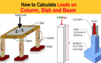
Column Load Calculation | Slab Load Calculation | Beam Load Calculation
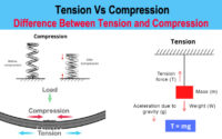
Difference between Tension and Compression | Tension Vs Compression
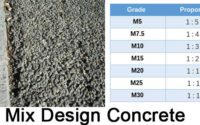
Mix Design Concrete Calculation – M20, M25, M30, M35
About The Author
John Steffen
I love to share my experience on civil engineering and construction estimates. As a highly capable individual with a strong academic background, I am proud to say that I already possess a comprehensive understanding of the technical elements of civil engineering.