
Basic Thumb Rules Column Construction | Column Construction Thum Rule
In this article, we will learn more about basic thump rules for column construction to be considered and followed. Of course, the design of the columns must take into account the total forces operating on the building, but aside from that, it is essential for every civil engineer and architect to remember a few general principles to prevent errors.
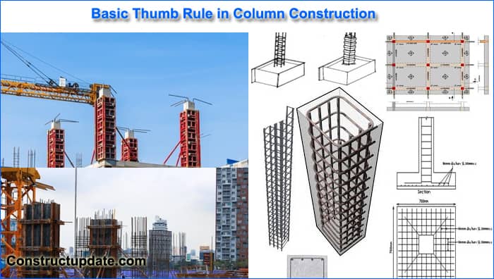
Following are three thumb rules for making a column layout
- Columns Size
- Distance Between Columns
- Alignment of columns
Minimum Size of RCC columns
The size of the columns is determined by the total load exerted on them. There are axial and lateral loads. Large beam spans pull the columns and cause bending moments in the beams as a result of the pressures. It’s essential to use cutting-edge structural design software like ETabs or Staad pro. These programmes ought to be taught to every structural designer, in my opinion. The general design principles apply to incredibly small tasks.
We’ll assume a structure with normal 6′′ walls and G+1 floors of height for the purposes of this rule of thumb.
A RCC column must be at least 9″ x 12″ (225mm x 300mm) in dimension and contain four 12 MM Fe415 steel bars.
These days, I only utilise 9′′ by 12′′ (225 mm x 300 mm) projects with 6 bars of 12 MM Fe500 steel. Strong columns are always a good choice. I also advise using M20 grade concrete (1 part cement, 1.5 parts sand, 3 parts aggregate, and 0.5 part water by volume) for the structure. Along the length of the column, I advise using 8 MM stirrups spaced 150 MM centre to centre.
For G+1 Floors, this arrangement of 9″ x 12″ RCC columns is secure. This is simply a general guideline; there are many additional factors to take into account.
Span (distance) between two columns
A spread of up to 5 metres is fairly safe for the above-mentioned column configuration. For spans up to 5 m, beams measuring 9′′ x 12′′ (225 mm x 300 mm) with a slab thickness of 5′′ (125 mm) can be cast in M20 concrete. Other factors that need to be taken into account are secondary and tertiary spans, point loads, and wall loads.
It is complicated, but if the structure is simple, general guidelines can be used. It is always advised to utilise structural design software for design, such as ETabs or Staad pro.
I can utilise steel as shown below in a beam up to 5 metres long with secondary spans up to 4 metres and wall loads up to 8 kN per running metre.
Top Steel – 2 bars of 12 MM
Two 12 MM crank bars spaced L/4 apart at both ends of a beam with simple support form the crank bars.
Bottom Steel – 3 bars of 12 MM.
Numerous variables can affect how this setup is configured.
Alignment of Columns
The plan determines exactly where the columns will be placed. A planner performs a crucial role. To avoid needless construction complexities and point loads, grid column arrangement is always favoured. Both the cost and time needed for construction are decreased as a result. In order to be safe, beams that are continuous with other simply supported beams have less bending moment and hence need less steel and concrete depth.
To facilitate the efficient transfer of loads, columns must be connected to one another. Such considerations will be taken into account by an experienced planner while designing the building.


Reinforcement Shape Codes | BBS Formula and Codes

What is Primer Paint | Types of Primer used in Construction

What is Fish Ladder | Fish Pass Structure | Fish Steps Structure
About The Author
John Steffen
I love to share my experience on civil engineering and construction estimates. As a highly capable individual with a strong academic background, I am proud to say that I already possess a comprehensive understanding of the technical elements of civil engineering.